FIOR & GENTZ
Gesellschaft für Entwicklung und Vertrieb von orthopädietechnischen Systemen mbH
Dorette-von-Stern-Straße 5
D-21337 Lüneburg
Tel.: +49 4131 24445-0
Fax: +49 4131 24445-57
E-Mail: info(at)fior-gentz.de
Beratung und Technischer Support

AFO
in Joint Lamination Technique
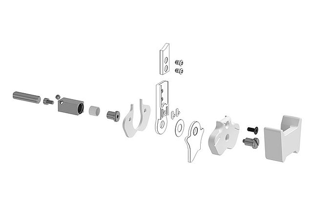
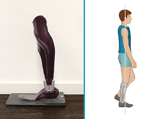
This online tutorial describes the production of an AFO (Ankle-Foot Orthosis) in Joint Lamination Technique. In contrast to the Anchor Lamination Technique, the system anchors and system cases are embedded into the laminate in the Joint Lamination Technique.
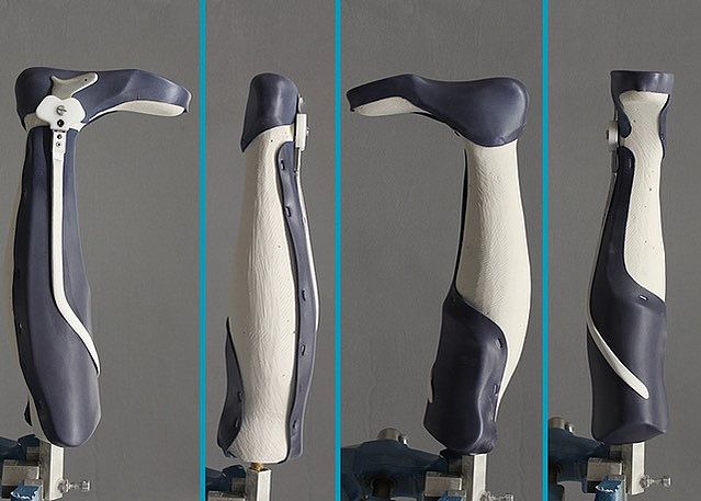
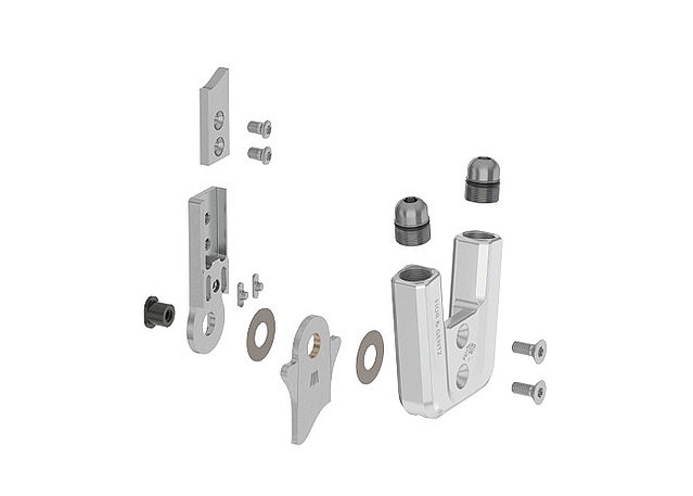
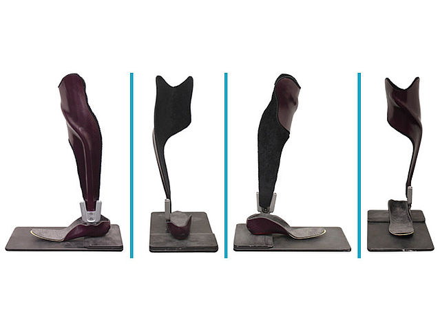
The exemplary orthosis with a NEURO SWING system ankle joint shows the following construction:
- unilateral
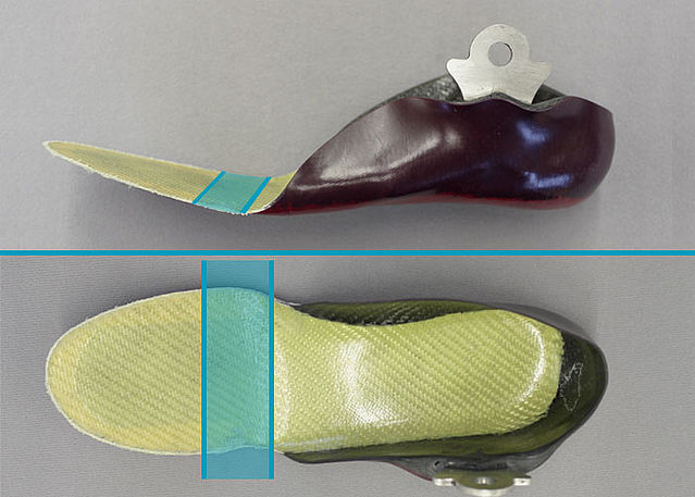
- partially flexible foot piece
- ventral shell
- Joint Lamination Technique
The presented production technique can also be applied to the NEURO CLASSIC-SWING and NEURO SWING-CLASSIC as well as the plug + go system joints, as it involves the same or similar system components.
You will find further work steps in the Joint Assembly NEURO SWING online tutorial.
-
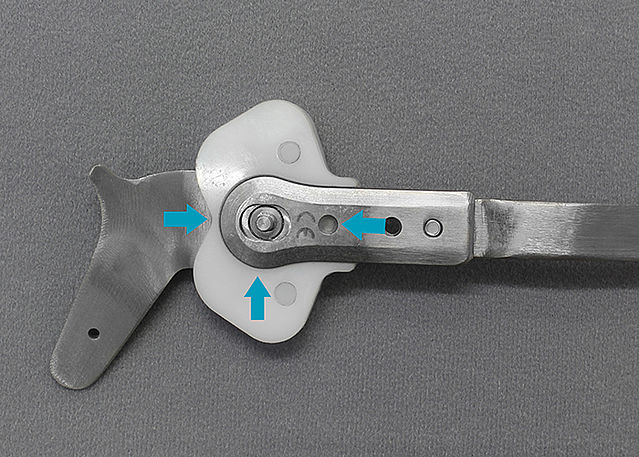
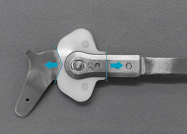
Mounting the Assembly/Lamination Dummy
-
Step 1/1
-
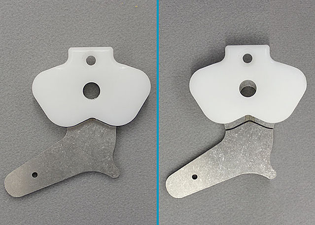
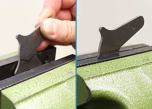
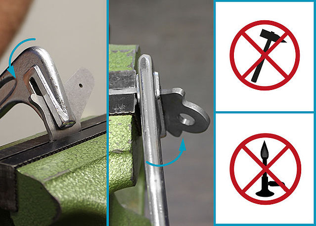
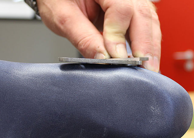
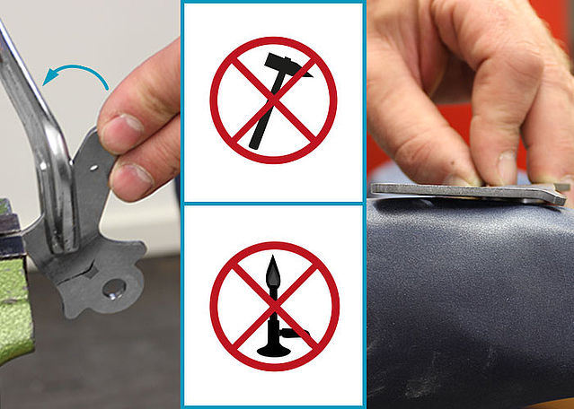
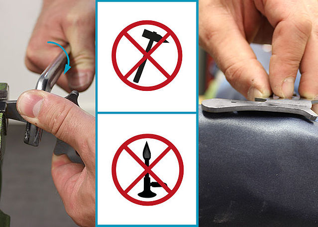
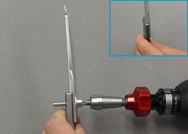
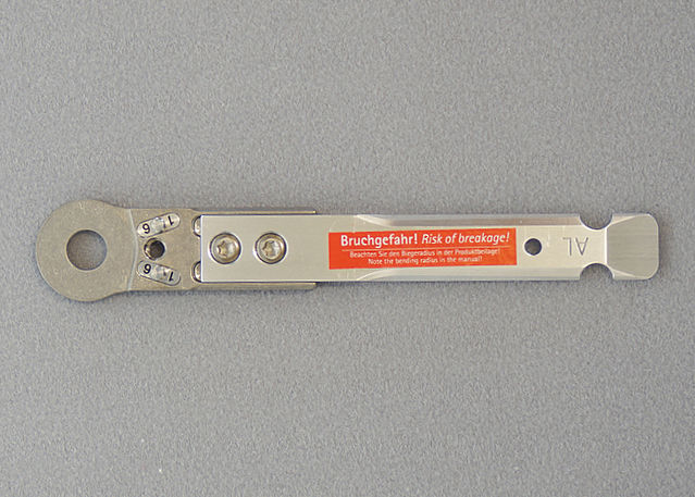
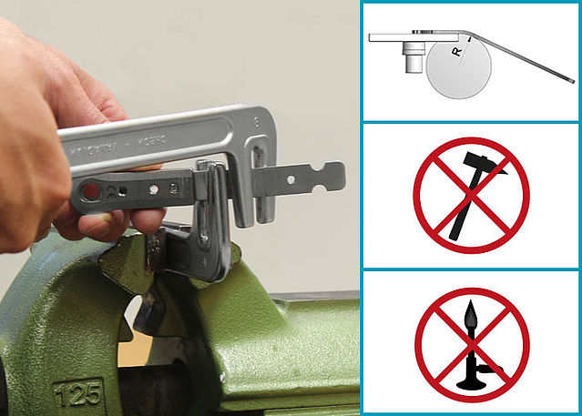
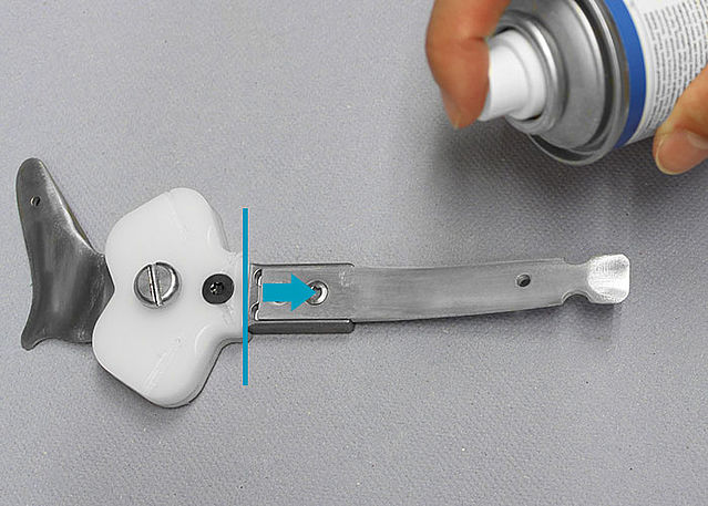
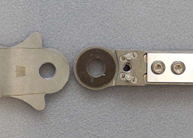
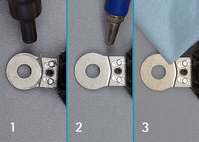
Bending the System Stirrup/Anchor
-
Step 1/11
Step 2/11
Step 3/11
Step 4/11
Step 5/11
Step 6/11
Step 7/11
Step 8/11
Step 9/11
Step 10/11
Step 11/11


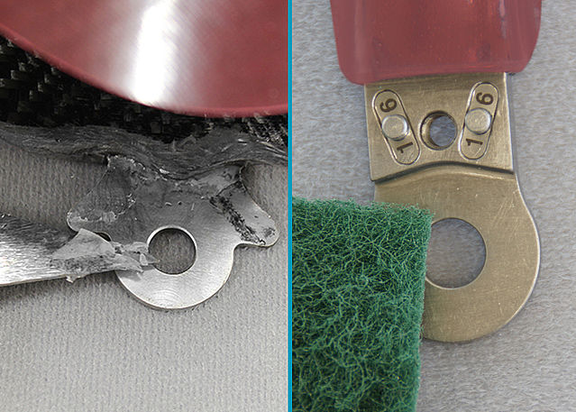
-
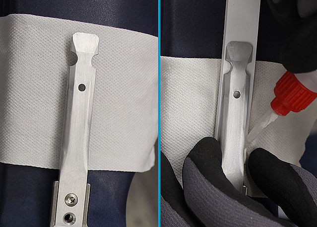
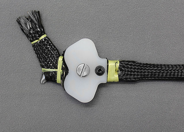
Preparing the System String
-
Step 1/12
Step 2/12
Step 3/12
Step 4/12
Step 5/12
Step 6/12
Step 7/12
Step 8/12
Step 9/12
Step 10/12
Step 11/12
Step 12/12


-
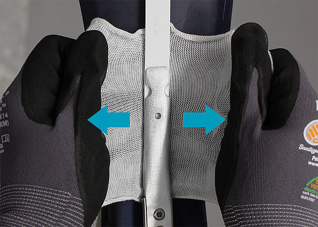
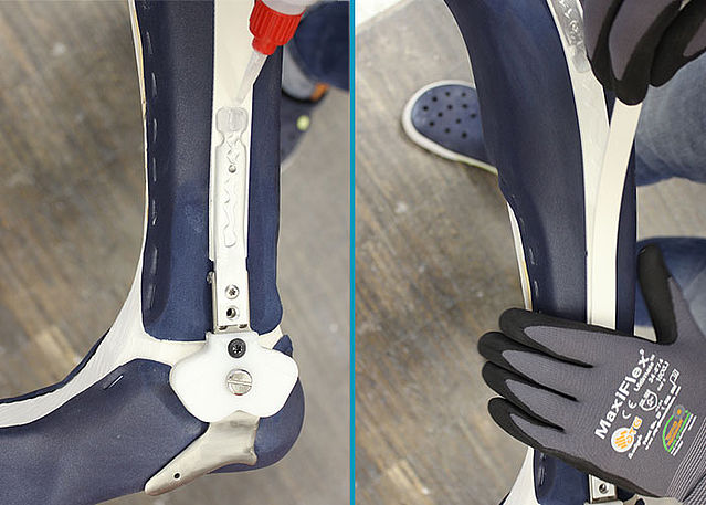
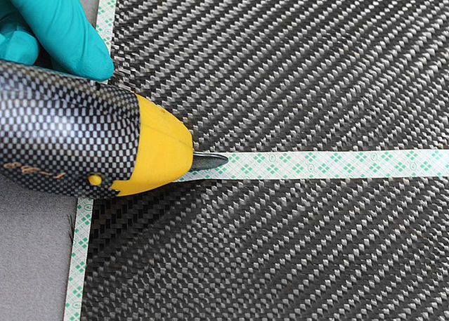
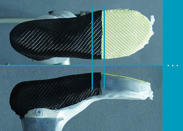
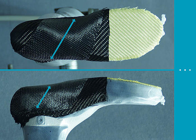
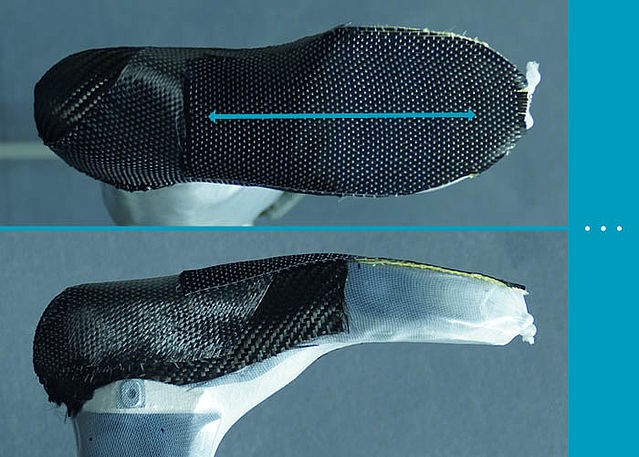
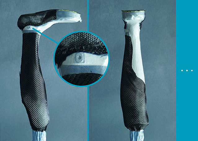
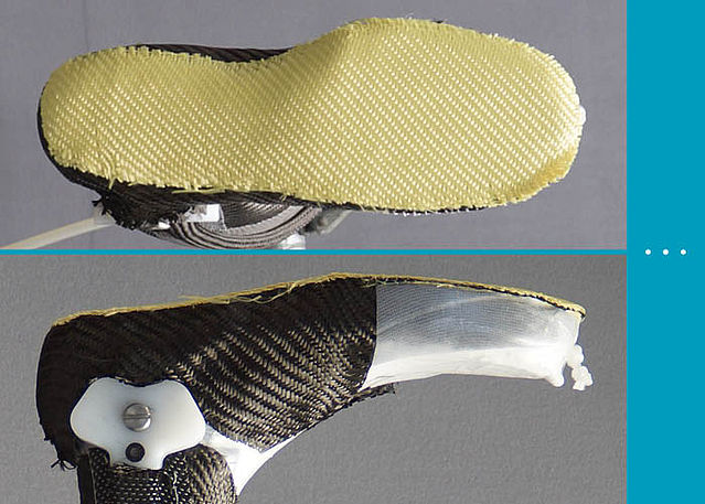
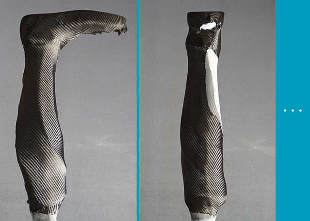
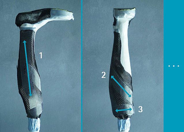
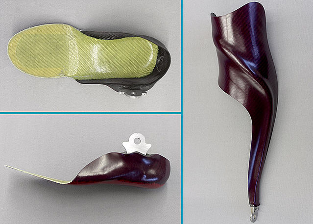
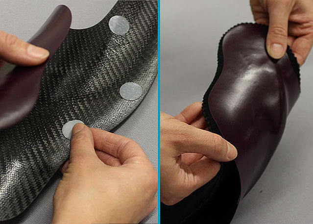
Reinforcing the AFO
-
Step 1/21
Step 2/21
Step 3/21
Step 4/21
Step 5/21
Step 6/21
Step 7/21
Step 8/21
Step 9/21
Step 10/21
Step 11/21
Step 12/21
Step 13/21
Step 14/21
Step 15/21
Step 16/21
Step 17/21
Step 18/21

Step 19/21
Step 20/21
Step 21/21


-
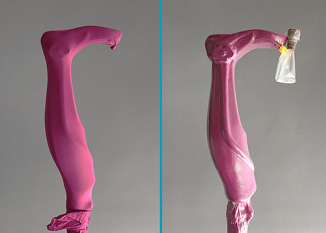
Laminating the AFO
-
Step 1/5
Step 2/5
Step 3/5

Step 4/5
Step 5/5


-
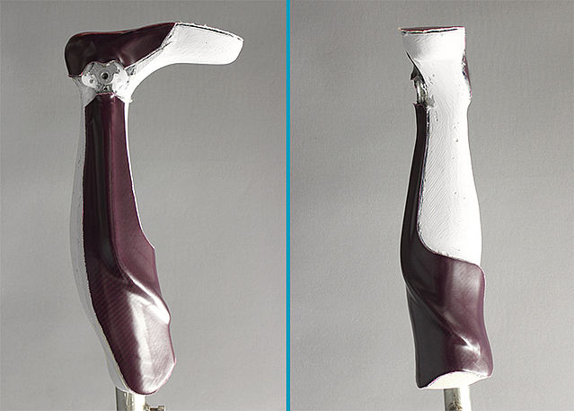
Cutting the AFO
-
Step 1/5
Step 2/5
Step 3/5
Step 4/5
Step 5/5


-
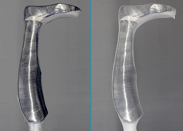
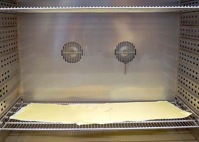
Tempering and Grinding the AFO
-
Step 1/4
Step 2/4
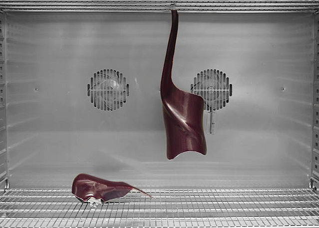
Step 3/4
Step 4/4


-
Mounting the System Joint
-
Step 1/1
-
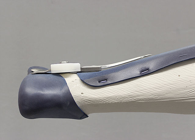
Applying the Padding Material
-
Step 1/3

Step 2/3
Step 3/3


-
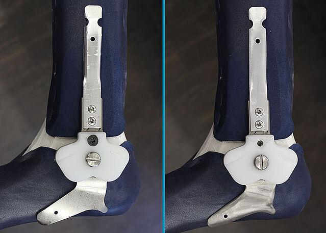
Alignment of the Orthosis
-
Step 1/1
Last Update: 12 October 2018
FIOR & GENTZ
Gesellschaft für Entwicklung und Vertrieb von orthopädietechnischen Systemen mbH
Dorette-von-Stern-Straße 5
D-21337 Lüneburg
Tel.: +49 4131 24445-0
Fax: +49 4131 24445-57
E-Mail: info(at)fior-gentz.de
Beratung und Technischer Support