FIOR & GENTZ

Gesellschaft für Entwicklung und Vertrieb von orthopädietechnischen Systemen mbH

Dorette-von-Stern-Straße 5
D-21337 Lüneburg

Tel.: +49 4131 24445-0
Fax: +49 4131 24445-57
E-Mail: info(at)fior-gentz.de

Joint Assembly Modular System Ankle Joints

Using NEURO SWING 2 as an Example

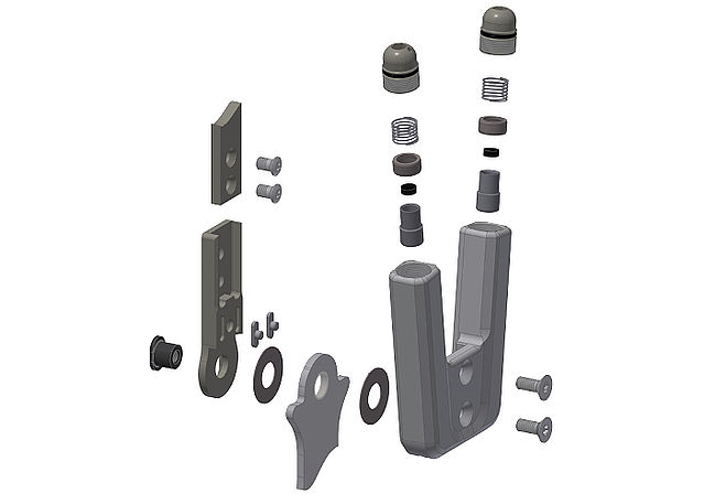
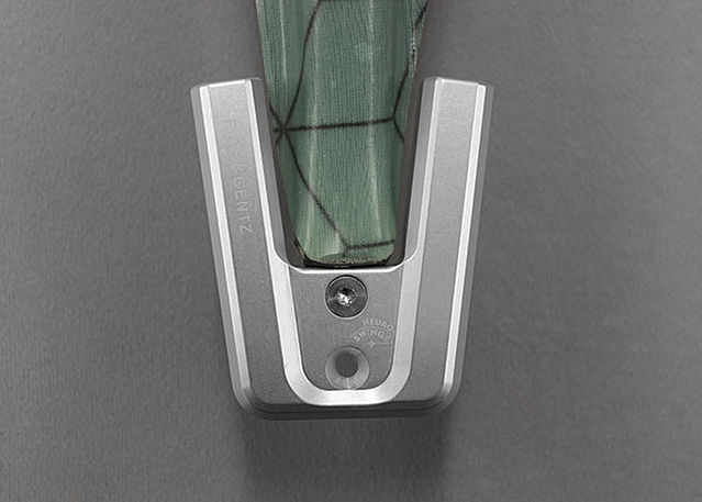
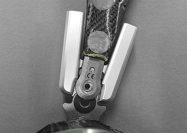
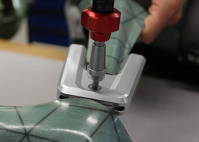
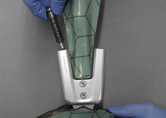
This online tutorial shows the joint assembly of our modular system ankle joints using the NEURO SWING 2 system ankle joint as an example.

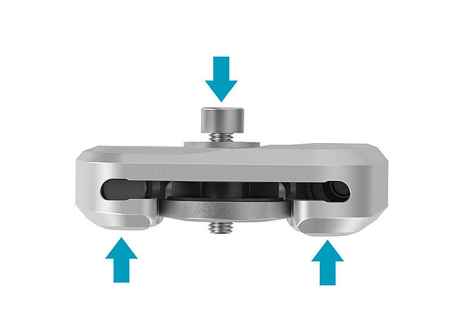
Besides its dynamic spring units, the NEURO SWING 2 system ankle joint provides an integrated noise reduction as well. You will find further information in the instructions for use.

Step 1/23

Demount the cover plate. 

Unscrew both countersunk flat head screws. Place the washer on the cover plate and screw the pressing screw (not entirely) into the thread of the first screw. Push the joint's upper part and the cover plate apart by exerting force on them (arrows). This can be achieved by using a vice or by controlled knocks.

Remove pressing screw and washer.

Step 2/23

Clean the system joint. In order to clean the threads in the cover plate, use the Super Clean LOCTITE® 7063 to remove any insulating wax residues.
Note: Mind the safety data sheet when using Super Clean LOCTITE® 7063.

Step 3/23

Apply spray adhesive to one side of the first sliding washer and adhere it to the cover plate. Grease the other side of the sliding washer slightly with orthosis joint grease.

Step 4/23

Use the delivered cover plate pressing aid to press the cover plate with the joint's upper part. Tighten the pressing screw with the corresponding torque.
Note: You will find the appropriate torque (Nm) on the cover plate of the system joint or in the instructions for use.

Step 5/23

Remove pressing screw and washer.
In order to fix the cover plate for the next work steps, screw in the first countersunk flat head screw with the torque which corresponds to the system width.

Step 6/23

Make sure there is no space left between the cover plate and the joint's upper part.

Step 7/23

Grease the second sliding washer slightly with orthosis joint grease.

Step 8/23

Grease the contact surfaces of the system stirrup between system stirrup and spring units with orthosis joint grease. Place the second sliding washer onto the medial side of the system stirrup.  

Step 9/23

Slide the system stirrup from below between the cover plate and the joint's upper part. Make sure that the sliding washer remains in the correct position.

Step 10/23

Check if the sliding washer fits well.

Step 11/23

Grease the friction surfaces of the bearing nut slightly with orthosis joint grease.

Step 12/23

Put the bearing nut into the intended opening of the joint's upper part and make sure that it is in the correct position. Secure the bearing nut with one finger.

Step 13/23

Screw in the second countersunk flat head screw (axle screw) with the torque which corresponds to the system width while fixing the bearing nut from the backside with one finger.  
If you have damaged a sliding washer while mounting the cover plate (you would hear a soft cracking), remove the particles and place a new sliding washer.

Step 14/23

Bring the system joint in plantar flexion/dorsiflexion. If the system joint does not move freely, mount the next thinner sliding washer, repeat all steps from step 7 onwards and check again.
Note: Check if the joint moves freely before mounting the spring units. At a bilateral orthosis, only check one system joint at a time.  

Step 15/23

Hold the tibial shell and try to move the foot piece in pronation-supination direction. If the system joint has lateral play, mount the next thicker sliding washer, repeat all steps from step 7 onwards and check again.
Note: Check if the joint runs with lateral play before mounting the spring units. At a bilateral orthosis, only check one system joint at a time.

Step 16/23

Secure both screws with LOCTITE 243® medium strength and the torque corresponding to the system width. Let the adhesive harden (final strength after approx. 24 hours).
Note: Mind the safety data sheet when using LOCTITE® 243 medium strength.

Step 17/23

Insert any present spring units.

Step 18/23

Place the orthosis on its forefoot and put weight on the system joint in dorsiflexion. Screw in any present spring units until the required alignment of the orthosis is achieved.

At a bilateral orthosis with two NEURO SWING 2 system joints, mount each system joint’s anterior spring unit and make sure that both system joints are adjusted alike.  

At a bilateral orthosis with a supporting joint, the range of motion of the
NEURO SWING 2 system joint should be limited without being restricted by the supporting joint. You might need to file off the stops of the supporting joint’s system stirrup.  

Step 19/23

Check the joint angle by reading the markings on the system stirrup and the cover plate.

Step 20/23

Adjust any present spring units for the plantar flexion.
Note: You will find information about the assembly of the spring units in the instructions for use.

At a bilateral orthosis with two NEURO SWING 2 system joints, mount each system joint’s posterior spring unit and make sure that both system joints are adjusted alike.   

At a bilateral orthosis with a supporting joint, the range of motion of the NEURO SWING 2 system joint should be limited without being restricted by the supporting joint. You might need to file off the stops of the supporting joint’s system stirrup.  

Step 21/23

Bring the system joint in plantar flexion/dorsiflexion. Any present spring units should move by compression only. At a high spring force, it might be impossible to cause any movement manually.
If the system joint still runs idle, carefully screw the posterior alignment screw further in.

Step 22/23

Grease the contact surfaces of the cover plate with orthosis joint grease to prevent friction noises between cover plate and joint’s upper part.

Step 23/23

Make sure that there is no contact between the laminate and the cover plate to prevent the development of noise under dynamic load.
If necessary, rework the laminate edges.
Make sure that you do not grind the lateral surfaces of the joint’s upper part. This can damage the fit between the joint’s upper part and the cover plate, which can lead to mechanical noises and to the breakage of the feather keys with pin.

Last Update: 16 November 2020

FIOR & GENTZ

Gesellschaft für Entwicklung und Vertrieb von orthopädietechnischen Systemen mbH

Dorette-von-Stern-Straße 5
D-21337 Lüneburg

Tel.: +49 4131 24445-0
Fax: +49 4131 24445-57
E-Mail: info(at)fior-gentz.de


×

Technische Cookies

Name Purpose Record Duration Provider Type
fe_typo_user This cookie is a standard session cookie of TYPO3. It stores the entered access data when a user logs in for a closed area. duration of the session TYPO3 Association, Sihlbruggstrasse 105, 6340 Baar, Schweiz HTTP
rc::c distinguishes between humans and bots duration of the session Google Ireland Limited, Google Building Gordon House, 4 Barrow St, Dublin, D04 E5W5, Irland HTML
×

Marketing Cookies

Name Purpose Record Duration Provider Type
_ga registers a unique ID which is used to generate statistical data on the user’s website usage 2 years Google Ireland Limited, Google Building Gordon House, 4 Barrow St, Dublin, D04 E5W5, Irland HTTP
_gid registers a unique ID which is used to generate statistical data on the user’s website usage 1 day Google Ireland Limited, Google Building Gordon House, 4 Barrow St, Dublin, D04 E5W5, Irland HTTP
_gat The _gat_UA cookie also contains the identity number (_gat_ <***>) of the Google Analytics account or website to which the cookie refers.  1 day Google Ireland Limited, Google Building Gordon House, 4 Barrow St, Dublin, D04 E5W5, Irland HTTP
_gcl_au is used by Google AdSense for advertising efficiency on web pages 3 months Google Ireland Limited, Google Building Gordon House, 4 Barrow St, Dublin, D04 E5W5, Irland HTTP
r/collect transmits data about the user’s device and behaviour to Google Analytics duration of the session Google Ireland Limited, Google Building Gordon House, 4 Barrow St, Dublin, D04 E5W5, Irland Pixel