FIOR & GENTZ
Gesellschaft für Entwicklung und Vertrieb von orthopädietechnischen Systemen mbH
Dorette-von-Stern-Straße 5
D-21337 Lüneburg
Tel.: +49 4131 24445-0
Fax: +49 4131 24445-57
E-Mail: info(at)fior-gentz.de
Beratung und Technischer Support

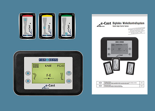
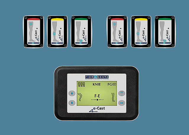
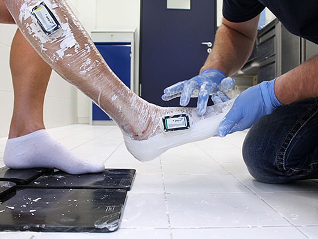
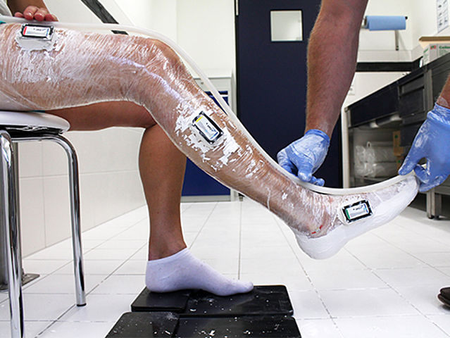
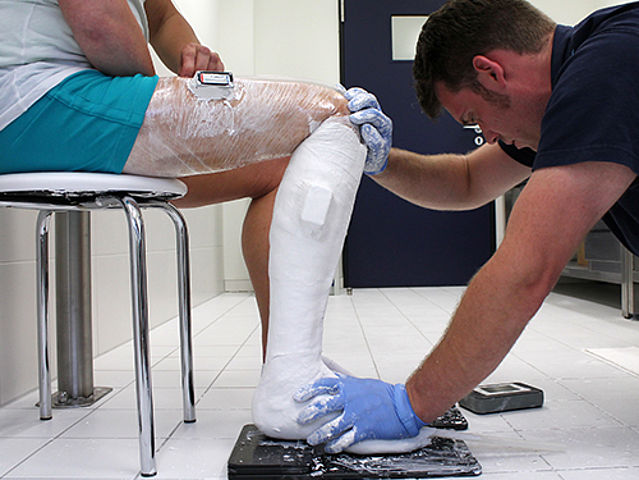
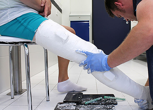
Making the Negative Cast with e-Cast
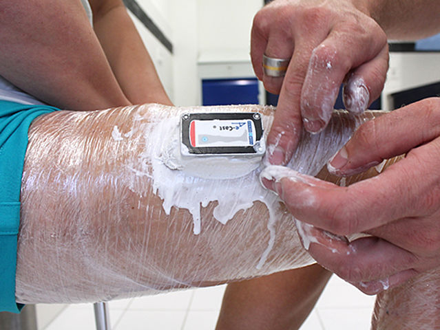
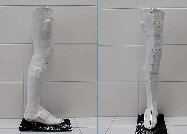
The plaster impression is the basis for producing a custom-made orthosis. The more precisely the negative cast is made, the better is the final result.
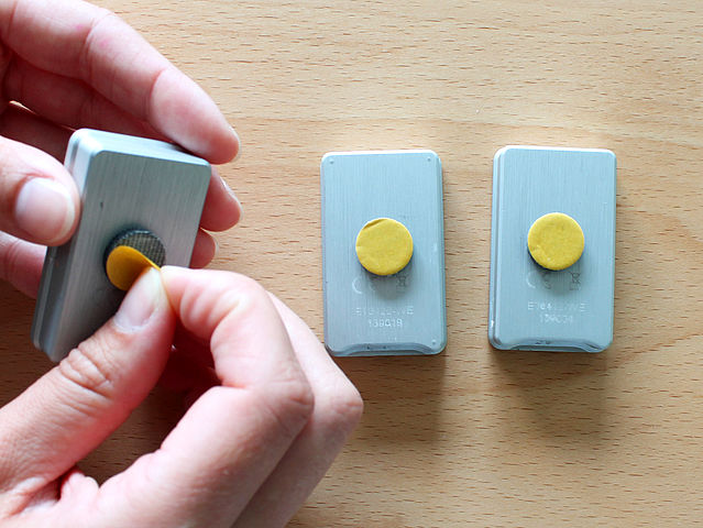
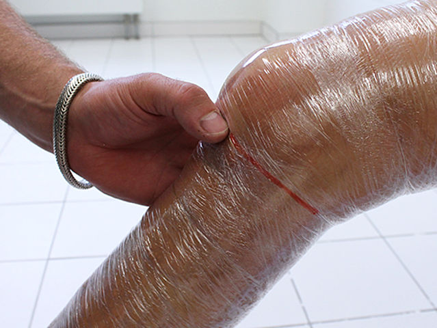
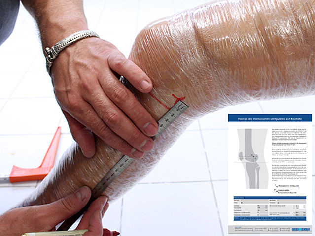
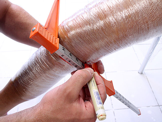
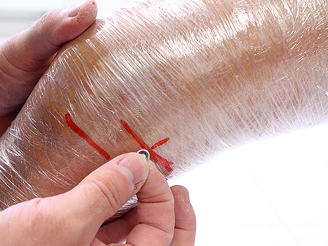
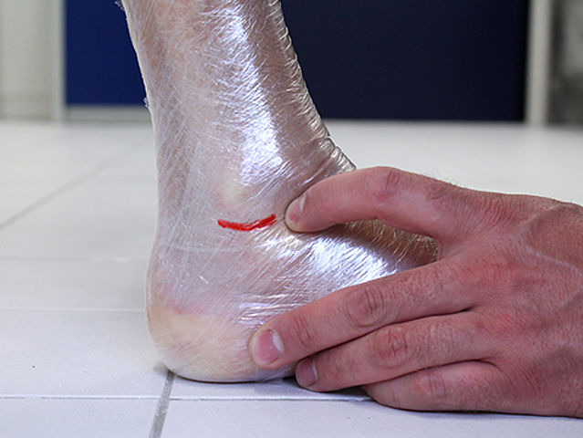
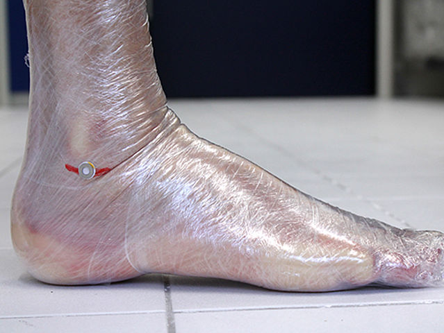
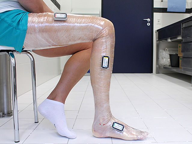
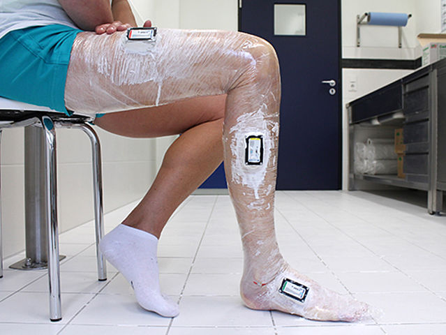
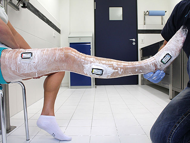
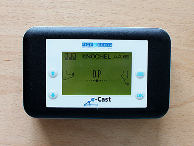
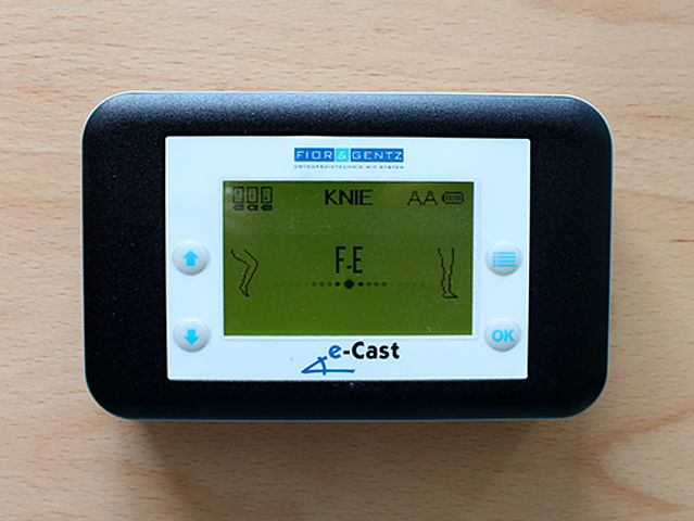
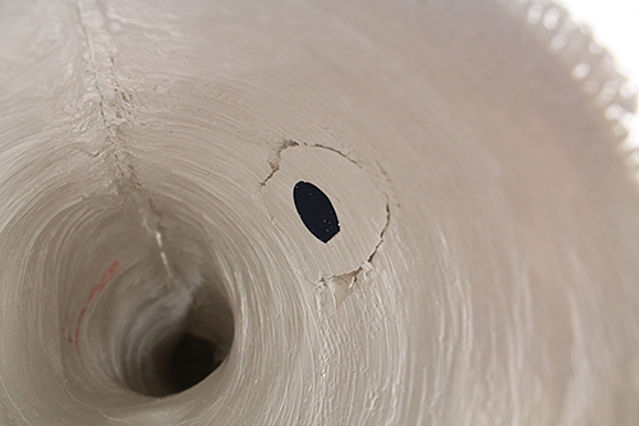
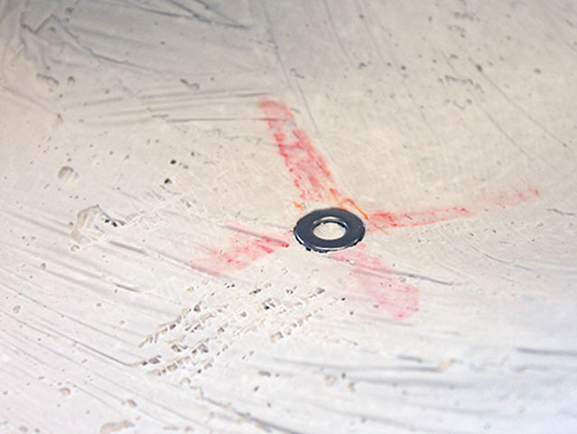
This production technique describes how to make the negative cast by using the digital casting aid e-Cast. Transferring the mechanical pivot points at ankle and knee height is an important factor in this process.
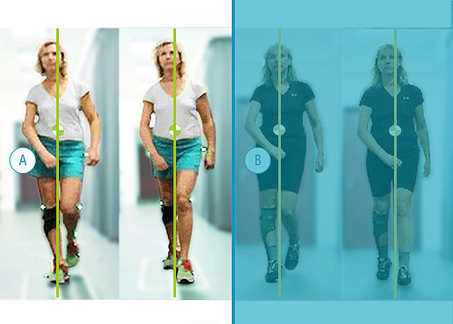
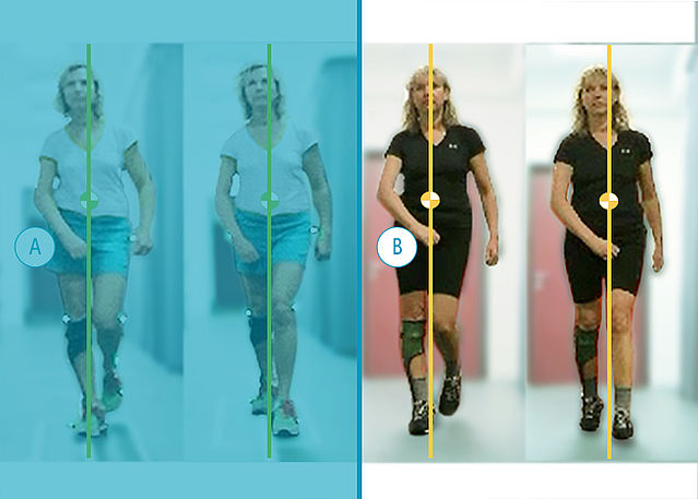
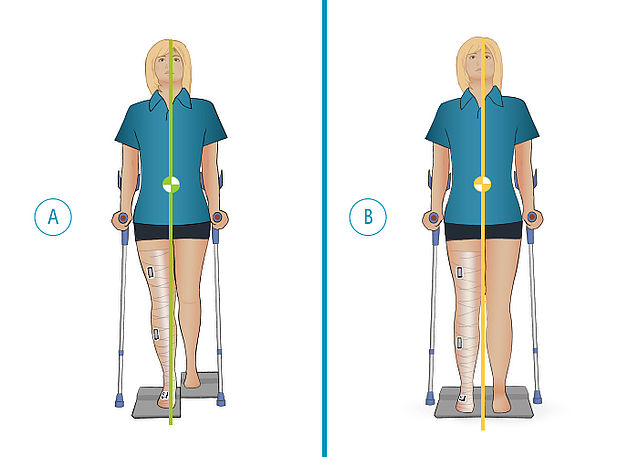
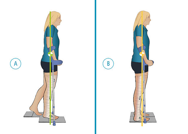
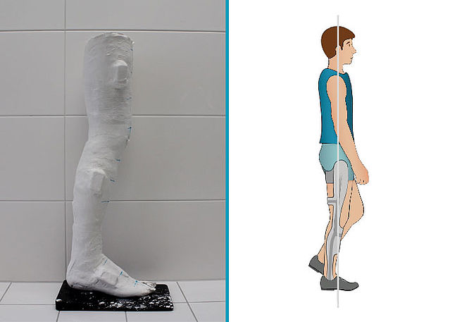
An application example shows which effect the patient's leg position while making the negative cast has on the final orthosis and therefore on the patient's gait.
-
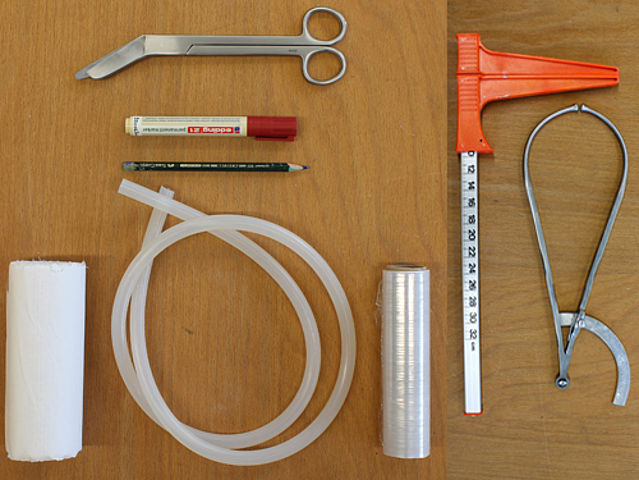
Preparing the Workspace
-
Step 1/4
Step 2/4
Step 3/4
Step 4/4


-
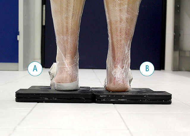
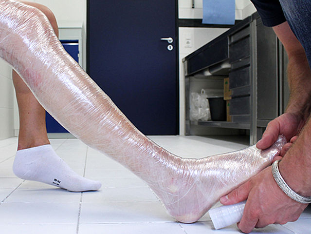
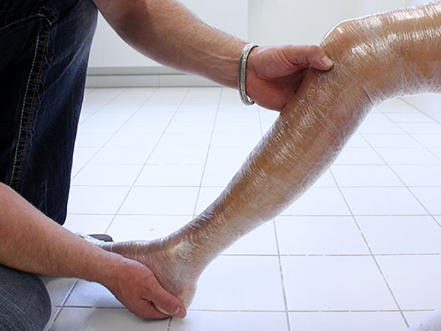
Preparing the Cast
-
Step 1/14
Step 2/14
Step 3/14
Step 4/14
Step 5/14
Step 6/14
Step 7/14
Step 8/14
Step 9/14
Step 10/14
Step 11/14
Step 12/14
Step 13/14
Step 14/14


-
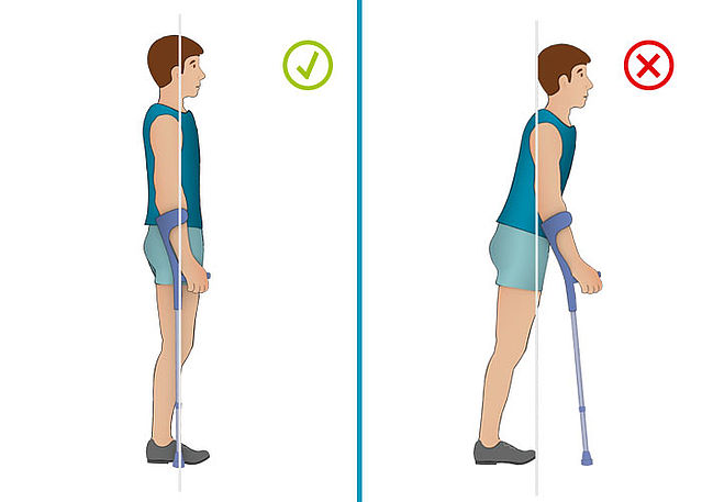
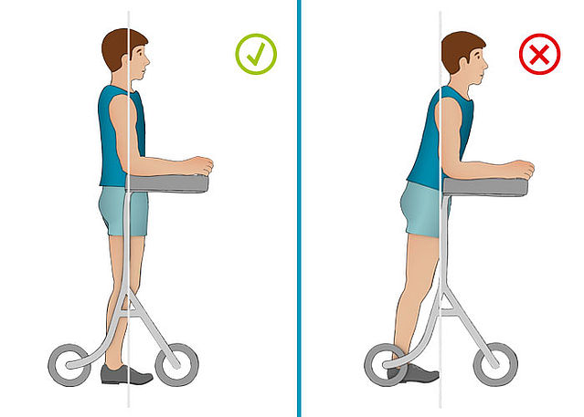
Determining the Ideal Position
-
Step 1/6
Step 2/6
Step 3/6
Step 4/6
Step 5/6
Step 6/6


-
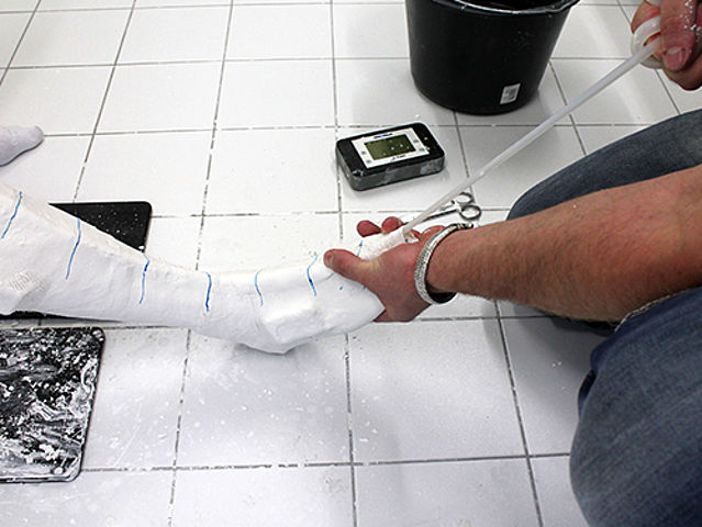
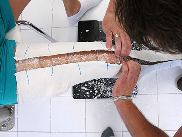
Making the Negative Cast
-
Step 1/11
Step 2/11
Step 3/11
Step 4/11
Step 5/11
Step 6/11
Step 7/11
Step 8/11
Step 9/11
Step 10/11
Step 11/11


-
Alignment of the Orthosis
-
Step 1/1
Last Update: 04 June 2019
FIOR & GENTZ
Gesellschaft für Entwicklung und Vertrieb von orthopädietechnischen Systemen mbH
Dorette-von-Stern-Straße 5
D-21337 Lüneburg
Tel.: +49 4131 24445-0
Fax: +49 4131 24445-57
E-Mail: info(at)fior-gentz.de
Beratung und Technischer Support