FIOR & GENTZ
Gesellschaft für Entwicklung und Vertrieb von orthopädietechnischen Systemen mbH
Dorette-von-Stern-Straße 5
D-21337 Lüneburg
Tel.: +49 4131 24445-0
Fax: +49 4131 24445-57
E-Mail: info(at)fior-gentz.de
Beratung und Technischer Support

Checking the Orthosis’ Alignment
Using the example of an AFO with NEURO SWING System Ankle Joint
When handing over the orthosis to the patient, you check the orthosis‘ alignment, make adjustments and change settings, if necessary. The following construction serves as an example:
- AFO
- unilateral
- partially flexible foot piece
- NEURO SWING system ankle joint
In this online tutorial, we put our main focus on checking the alignment dynamically on the patient. It refers to unilaterally treated patients whose contralateral side is without restrictions. The AFO should be produced according to our treatment concept, which we illustrate in our online tutorials.
-
Preparations
-
Step 1/3
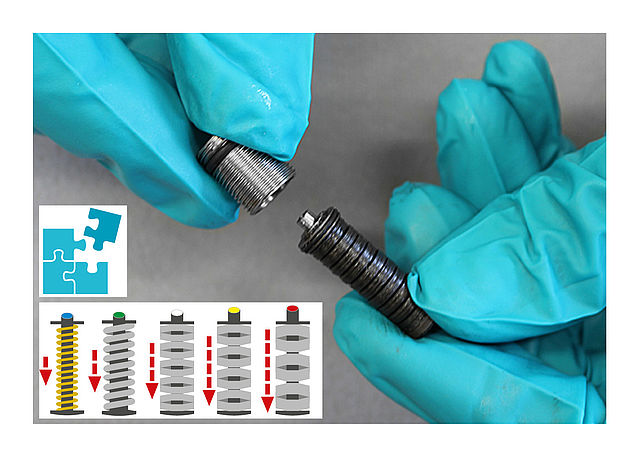
Step 2/3
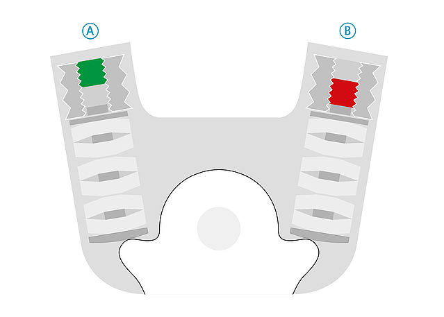
Step 3/3


-
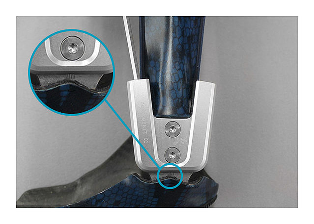
On the Workbench
-
Step 1/1
-
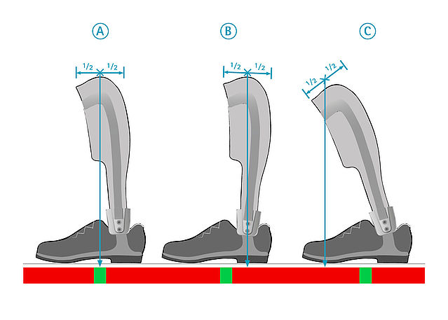
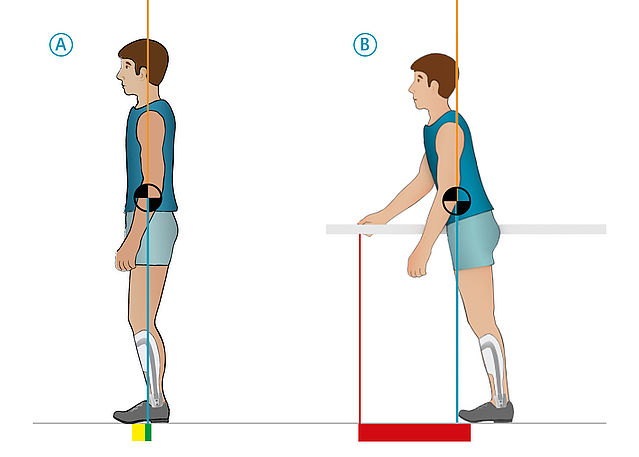
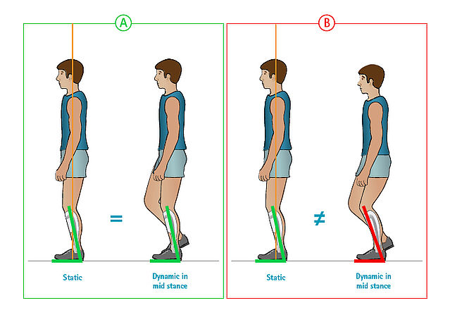
Statically on the Patient
-
Step 1/1
-
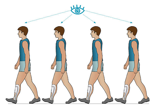
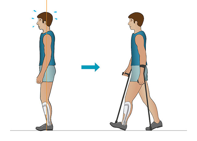
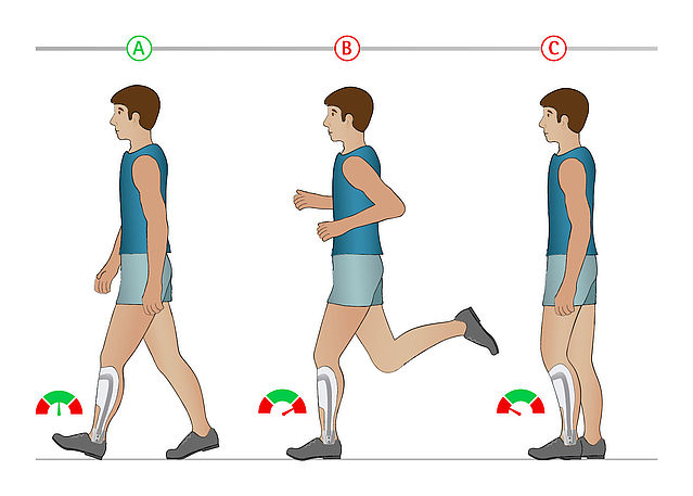
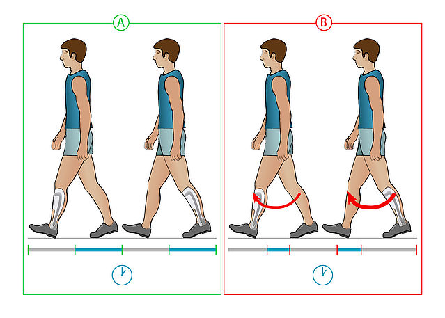
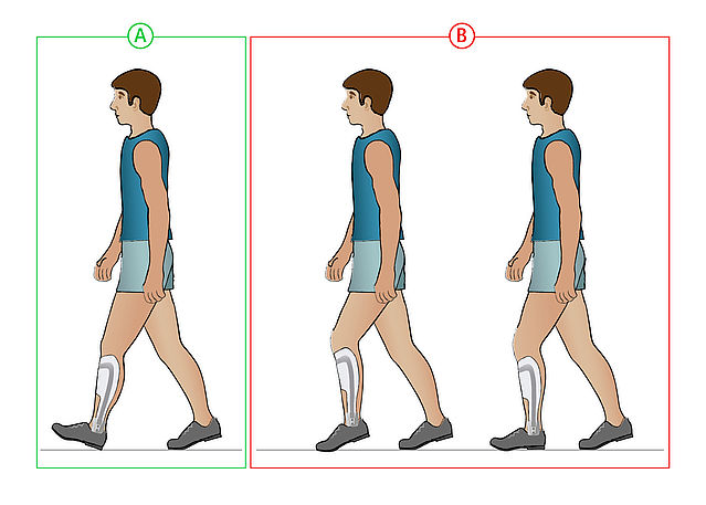
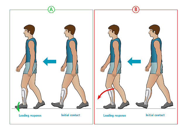
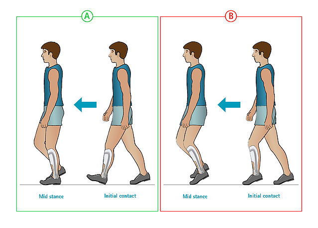
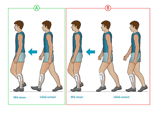
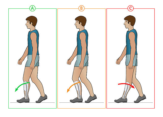
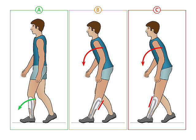
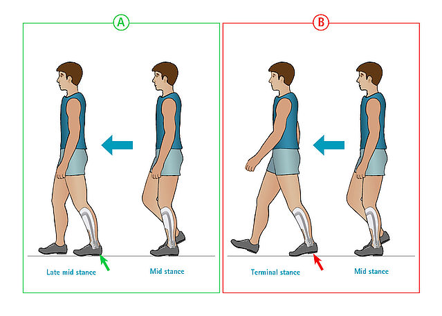
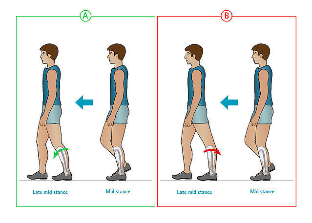
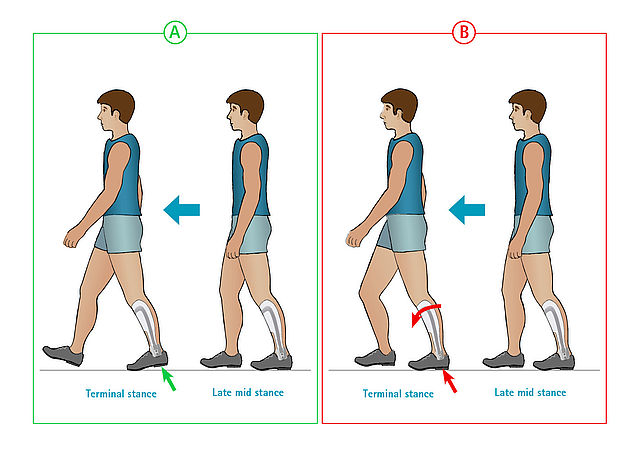
Dynamically on the Patient
-
Step 1/14
Step 2/14
Step 3/14
Step 4/14
Step 5/14
Step 6/14
Step 7/14
Step 8/14
Step 9/14
Step 10/14
Step 11/14
Step 12/14
Step 13/14
Step 14/14


Last Update: 20 March 2020
FIOR & GENTZ
Gesellschaft für Entwicklung und Vertrieb von orthopädietechnischen Systemen mbH
Dorette-von-Stern-Straße 5
D-21337 Lüneburg
Tel.: +49 4131 24445-0
Fax: +49 4131 24445-57
E-Mail: info(at)fior-gentz.de
Beratung und Technischer Support